- 您现在的位置:买卖IC网 > Sheet目录311 > AS5045 PB (ams)BOARD PROGRAM AS5045
�� �
�
�Following� the� 18� clock� (after� reading� bit� “ccw”),� the� chip� must� be� reset� by� disconnecting� the� power� supply.�
�AS5045�
�Data� Sheet�
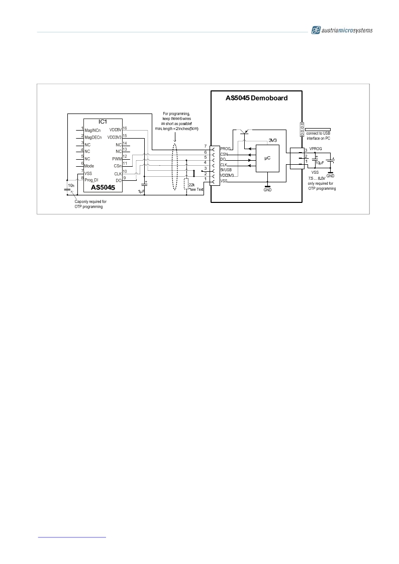
�Figure� 12.� OTP� Programming� Connection� of� AS5045� (shown� with� AS5045� demoboard)�
�11.4� Analog� Readback� Mode�
�Non-volatile� programming� (OTP)� uses� on-chip� zener� diodes,� which� become� permanently� low� resistive� when�
�subjected� to� a� specified� reverse� current.�
�The� quality� of� the� programming� process� depends� on� the� amount� of� current� that� is� applied� during� the� programming�
�process� (up� to� 130mA).� This� current� must� be� provided� by� an� external� voltage� source.� If� this� voltage� source� cannot�
�provide� adequate� power,� the� zener� diodes� may� not� be� programmed� properly.�
�In� order� to� verify� the� quality� of� the� programmed� bit,� an� analog� level� can� be� read� for� each� zener� diode,� giving� an�
�indication� whether� this� particular� bit� was� properly� programmed� or� not.�
�To� put� the� AS5045� in� Analog� Readback� Mode,� a� digital� sequence� must� be� applied� to� pins� CSn,� PROG� and� CLK� as�
�shown� in� Figure� 13� .� The� digital� level� for� this� pin� depends� on� the� supply� configuration� (3.3V� or� 5V;� see� section� 13�
�3V� /� 5V� Operation).�
�The� second� rising� edge� on� CSn� (OutpEN)� changes� pin� PROG� to� a� digital� output� and� the� log.� high� signal� at� pin� PROG�
�must� be� removed� to� avoid� collision� of� outputs� (grey� area� in� Figure� 13� ).�
�The� following� falling� slope� of� CSn� changes� pin� PROG� to� an� analog� output,� providing� a� reference� voltage� V� ref� ,� that�
�must� be� saved� as� a� reference� for� the� calculation� of� the� subsequent� programmed� and� unprogrammed� OTP� bits.�
�Following� this� step,� each� rising� slope� of� CLK� outputs� one� bit� of� data� in� the� reverse� order� as� during� programming�
�(see� Figure� 10� :� Md0-MD1-Div0,Div1-Indx-Z0…Z11,� ccw).�
�If� a� capacitor� is� connected� to� pin� PROG,� it� should� be� removed� during� analog� readback� mode� to� allow� a� fast� readout�
�rate.� If� the� capacitor� is� not� removed� the� analog� voltage� will� take� longer� to� stabilize� due� to� the� additional� capacitance.�
�The� measured� analog� voltage� for� each� bit� must� be� subtracted� from� the� previously� measured� V� ref� ,� and� the� resulting�
�value� gives� an� indication� on� the� quality� of� the� programmed� bit:� a� reading� of� <100mV� indicates� a� properly�
�programmed� bit� and� a� reading� of� >1V� indicates� a� properly� unprogrammed� bit.�
�A� reading� between� 100mV� and� 1V� indicates� a� faulty� bit,� which� may� result� in� an� undefined� digital� value,� when� the�
�OTP� is� read� at� power-up.�
�th�
�www.austriamicrosystems.com�
�Revision� 1.7�
�20� –� 33�
�发布紧急采购,3分钟左右您将得到回复。
相关PDF资料
AS5134 PB
BOARD PROGRAM AS5134
AS5140 PB
BOARD PROGRAM AS5140
ASDMB-ADAPTER-KIT
ASDMB MEMSPEED P II OSC KIT
ASFLMPLP-ADAPTER-KIT
ASFLMPLP MEMSPEED P II OSC KIT
AT24C01-10SI-1.8
IC EEPROM 1KBIT 400KHZ 8SOIC
AT24C01B-TSU-T
IC EEPROM 1KBIT 1MHZ SOT23-5
AT24C02C-XHM-B
IC EEPROM 2KBIT 1MHZ 8TSSOP
AT24C04AN-10SI-2.7
IC EEPROM 4KBIT 400KHZ 8SOIC
相关代理商/技术参数
AS5045_V1
制造商:AMSCO 制造商全称:austriamicrosystems AG 功能描述:12 Bit Programmable Magnetic Rotary Encoder
AS5045-AB
制造商:ams 功能描述:AS5045 Adapter Board
AS5045-ADAPTER
制造商:AMS 功能描述:Adapter Board to Test and Evaluate AS5045 Rotary Encoder
AS5045ASST
制造商:ams 功能描述:T&R / SSOP 16
AS5045-ASST
功能描述:IC ENCODER PROG 12-BIT 16-SSOP RoHS:是 类别:传感器,转换器 >> 磁性 - 霍尔效应,数字式开关,线性,罗盘 (IC) 系列:- 标准包装:1 系列:- 传感范围:20mT ~ 80mT 类型:旋转 电源电压:4.5 V ~ 5.5 V 电流 - 电源:15mA 电流 - 输出(最大):- 输出类型:数字式,PWM,8.5 位串行 特点:可编程 工作温度:-40°C ~ 150°C 封装/外壳:20-SSOP(0.209",5.30mm 宽) 供应商设备封装:20-SSOP 包装:Digi-Reel® 其它名称:AS5132-HSST-500DKR
AS5045ASSU
制造商:AMS 功能描述:IC MAGNETIC ROTARY ENCODER 12BIT SSOP16 制造商:AMS 功能描述:IC, MAGNETIC ROTARY ENCODER 12BIT SSOP16 制造商:AMS 功能描述:IC, MAGNETIC ROTARY ENCODER 12BIT SSOP16; IC Function:Encoder IC; Brief Features:360 Contactless High Resolution Angular Position Encoding, Two 12-bit Absolute Output; Supply Voltage Min:3V; Supply Voltage Max:3.6V; No. of Pins:16 ;RoHS Compliant: Yes
AS5045-ASSU
功能描述:板机接口霍耳效应/磁性传感器 RoHS:否 制造商:Honeywell 类型:Bipolar Hall-Effect Digital Position Sensor 工作电源电压:3 V to 24 V 电源电流:3.5 mA 最大输出电流:20 mA 工作点最小值/最大值:5 G, 55 G 最小/最大释放点(Brp):- 55 G, - 5 G 最大工作温度:+ 150 C 安装风格:SMD/SMT 封装 / 箱体:SOT-23
AS5045B
制造商:AMSCO 制造商全称:austriamicrosystems AG 功能描述:12-Bit Programmable Magnetic Position Sensor